
Delta vs wye is the choice between two ways of connecting the three windings of a transformer or generator. A wye (star) connection joins one end of each winding at a common neutral point. A delta connection joins the windings end to end in a closed loop, with no neutral. The choice sets the voltages a system offers, the currents its windings carry, the phase shift across a transformer and how the system is grounded.
For a buyer, the connection is part of what makes a transformer fit. A used unit with the right kVA and voltages can still be the wrong unit if its connection, phase shift or neutral arrangement differs from the system it joins. The transformers hub lists the models SecondWatt tracks; this article covers the connection data to read on each nameplate.
Key Takeaways
- In a wye connection, line voltage is √3 times phase voltage. A 480 V wye system has 277.1 V line to neutral; 208 V gives 120.1 V.
- In a delta connection, line current is √3 times winding current. With 1,000 A of balanced line current, each delta winding carries 577.4 A.
- A delta-wye transformer adds a neutral and a phase shift. Under ANSI convention the low side lags by 30°: Dy1 in IEC notation, Dyn1 with the neutral brought out.
- A nameplate's phase shift assumes ABC sequence and standard bushing connections. When the system sequence runs opposite to the bushing order, the actual shift is the nameplate's mirror image.
- A standard generator's neutral should be grounded through an impedance, SEL advises. Its single-phase-to-ground fault current can exceed three-phase fault current, and NEMA standards do not require bracing for that.
Delta vs wye: how the windings connect#
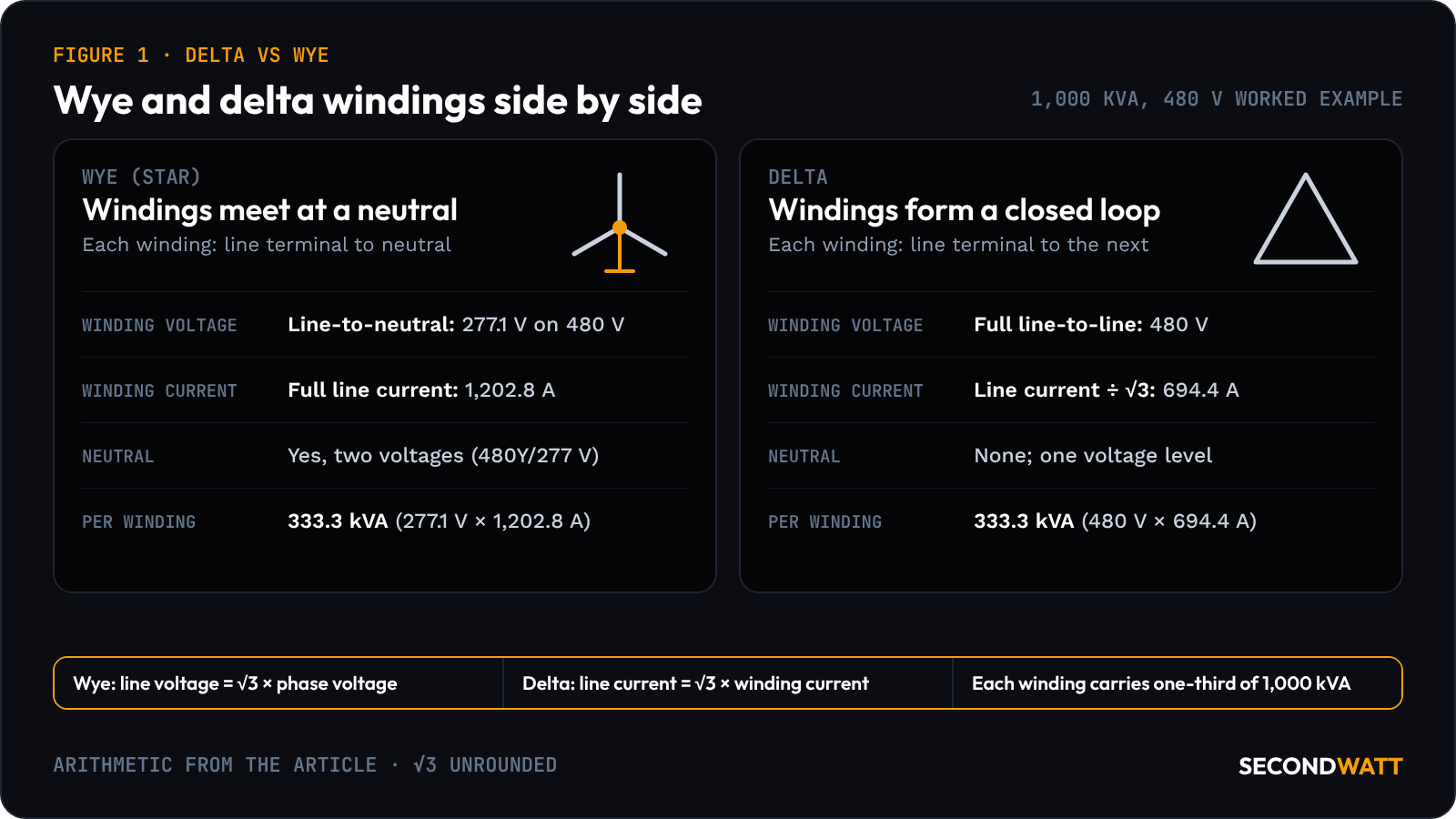
Three windings can be joined in two ways. In wye, each winding runs from a line terminal to the shared neutral, so it sees line-to-neutral voltage and carries the full line current. In delta, each winding runs from one line terminal to the next, so it sees the full line-to-line voltage and shares each line current with its neighbor. Wye vs delta is therefore a trade between a neutral and two voltage levels on one side, and a closed loop with one voltage level on the other.
On some machines the same windings can be reconnected either way. Revision F of Cummins' Stamford S6L1D-F4 technical data sheet, dated 24 Sep 2025, shows this for winding 311/312. That winding gives 480 V in series star, 277 V in delta and, with the 12-lead option, 240 V in parallel star, all at 60 Hz.
Voltage and current in each connection#
In a balanced wye connection, line-to-line voltage equals √3 × line-to-neutral voltage, and line current equals winding current. In a balanced delta connection, line-to-line voltage equals winding voltage, and line current equals √3 × winding current. Post Glover's technical information sheet NG112-06, dated 2012, states that on a wye secondary, line-to-neutral voltage equals system voltage divided by 1.732.
Line and phase voltages at US system voltages named in the cited documents (arithmetic V ÷ √3, to one decimal; voltages from Square D catalog 0100CT2401, Stamford S6L1D-F4 revision F and Post Glover NG112-06)#
| Line-to-line voltage | Wye winding (line-to-neutral) | Delta winding | Where the voltage appears in the cited documents |
|---|---|---|---|
| 208 V | 120.1 V | 208 V | Square D 208Y/120 dry-type secondaries |
| 480 V | 277.1 V | 480 V | Square D 480Y/277 secondaries; Stamford S6L1D-F4 at 480 V star, 60 Hz |
| 4,160 V | 2,401.8 V | 4,160 V | Post Glover's resistance-grounding example (rounded there to 2,400 V) |
| 13,800 V | 7,967.4 V | 13,800 V | Post Glover's 13,800Y/7970 V system diagram |
Voltage designations round the line-to-neutral figure: 13,800Y/7970 V in Post Glover's diagram, while 13,800 ÷ √3 = 7,967.4 V.
Current follows the same factor. A delta winding on a system with 1,000 A of balanced line current carries 1,000 ÷ √3 = 577.4 A. Full-load current for 1,000 kVA at 480 V three-phase is 1,203 A in a table in Square D's 2008 dry-type transformer pocket guide. To one decimal, 1,000,000 ÷ (√3 × 480) = 1,202.8 A.
Worked example on that 1,000 kVA, 480 V unit:
- Wye winding: 277.1 V × 1,202.8 A = 333.3 kVA per winding.
- Delta winding: 1,202.8 ÷ √3 = 694.4 A, and 480 V × 694.4 A = 333.3 kVA per winding.
Both connections carry one-third of 1,000 kVA in each winding. The wye winding sees less voltage and more current; the delta winding sees more voltage and less current.
333.3 kVA — the full-load share of each winding of a 1,000 kVA, 480 V transformer in either connection: 277.1 V × 1,202.8 A in wye, 480 V × 694.4 A in delta.
Delta-wye transformers on site#
The delta-wye pattern runs through Square D's low-voltage dry-type range. Its three-phase dry-type selection steps take a 208, 240, 480 or 600 V delta primary. Section 14 of Square D catalog 0100CT2401, dated 8/11/2026, lists secondaries of 208Y/120, 480Y/277 or 240 V delta with a 120 V center tap.
The wye secondary supplies a neutral. That neutral serves line-to-neutral loads such as single-phase lighting. High-resistance grounding gives up that use of the neutral, a drawback Post Glover lists in NG112-06.
Current that is equal and in phase in all three windings at once is zero-sequence current. In a wye-delta grounding transformer, the delta secondary is a closed series circuit for it, so a ground fault sees only the transformer's leakage reactance. In NG112-06, Post Glover notes that the fault's own resistance and the grounding resistor set the rest of the limit.
Harmonic loads are another use: 30° phase-shift delta-wye units, 480 V delta to 208Y/120 V, that "mitigate the harmful effects of triplens," in the words of Square D's catalog.
Pad-mount units can come in either connection. On Prolec GE's three-phase pad-mount line, high voltage runs up to 34,500 V and low voltage up to 1,200 V, each delta or wye connected. The figures come from its 2024 three-phase pad-mounted data sheet. The Howard Industries pad-mount and Hitachi Energy liquid-filled substation pages cover two other families.
A GSU transformer reverses the arrangement. Prolec GE's generator step-up transformer page gives typical ratings of 13.2 to 25 kV delta on the low-voltage side and 69 to 765 kV wye on the high-voltage side. The delta faces the generator; the wye faces the transmission line. The GE Prolec GSU dossier summarizes the line, and data center transformers covers where each type sits.
IEEE's guide for applying transformer connections is C57.105-2019, with Corrigendum 1-2023. Its IEEE SA listing gives the scope. The guide considers all combinations of delta and wye, grounded and ungrounded, T-connected, zigzag and certain special connections, for two-winding and autotransformers only.
Vector groups and phase shift#
A delta-wye transformer shifts phase between its two sides in steps of 30°. International practice records the shift as a vector group, explained in edition 3.0 of IEC 60076-1:2011. That standard is the reference SEL's "Beyond the Nameplate" paper gives for the notation.
In that notation, the capital letter is the high-voltage connection, the lowercase letter the low-voltage connection, and "n" means the neutral is brought out. In the April 2019 revision of SEL's paper, "Beyond the Nameplate," the number counts the 30° steps by which the low side lags the high side, for ABC phase sequence.
Vector groups named in the cited documents, read with IEC 60076-1 notation (SEL papers, 2019 and 2023; AEP/SEL paper, 2010; Schneider Electric Trihal catalog NRJCAT21019EN, July 2021)#
| Notation | Windings | Low side relative to high side | Where it appears in the cited documents |
|---|---|---|---|
| Dyn1 | Delta high side; wye low side with neutral brought out | Lags by 30° (1 × 30°) | SEL's standard DABY delta-wye example; the AEP and SEL paper's "typical distribution power bank" (Dy1) |
| Dyn11 | Delta high side; wye low side with neutral brought out | Lags by 330° (11 × 30°), which is a 30° lead | Listed first of three groups (Dyn 11, Dyn 5, Dyn 1) in Schneider Electric's Trihal cast resin catalog |
| Dyn5 | Delta high side; wye low side with neutral brought out | Lags by 150° (5 × 30°) | Listed second of the same three groups in the Trihal catalog |
| Dd2 | Delta high side; delta low side | Lags by 60° (2 × 30°) | SEL's 2023 "Beyond the Nameplate" paper, an example of two delta windings that are not in phase |
| Yyd1 | Wye primary and secondary; delta tertiary | Tertiary lags both wye sides by 30° | The AEP and SEL paper's "typical autotransformer" |
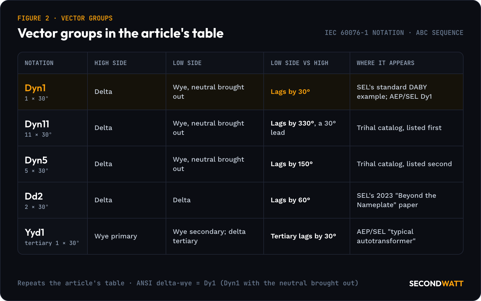
Transformers built to ANSI standards do not use vector groups; the nameplate carries a vector diagram instead. For delta-wye or wye-delta transformers, the standard puts the low-voltage side 30° behind the high-voltage side. Zhang and Smith, engineers from AEP and SEL, summarize it that way in "Lessons Learned in Vector Matching," their 2010 paper.
Their reference for the nameplate vector diagram is IEEE C57.12.00-2006. IEEE SA lists C57.12.00-2021 as the active edition.
In IEC terms the ANSI delta-wye unit is a Dy1, the group the AEP/SEL paper gives for a typical distribution power bank. With the wye side grounded, SEL's standard example is written Dyn1. The nameplate shift assumes two things: ABC system phase sequence and standard phase-to-bushing connections. SEL's "Beyond the Nameplate" paper notes that when the system sequence runs opposite to the bushing order, the actual shift is the nameplate's mirror image.
Generator connections and grounding#
Reconnecting an alternator also changes the current figures read from its data sheet. The Stamford S6L1D-F4 curves are drawn for star connection. For series delta, the data sheet multiplies curve current by 1.732, and for parallel star by 2.
A synchronous generator's zero-sequence impedance is typically about half its subtransient reactance. As a result, a single-phase-to-ground fault produces more current per phase than a three-phase fault. NEMA standards do not require standard generators to be braced for that.
The neutral of a standard generator should therefore be grounded through an impedance, keeping ground-fault current no greater than three-phase fault current. SEL draws that conclusion in "Understanding Generator Stator Ground Faults and Their Protection Schemes," a 2016 paper concerned primarily with synchronous generators connected to the grid through a GSU.
Grounding methods used in practice, as listed in IEEE C37.101-2006 and quoted by SEL in "Injection-Based Generator Stator Ground Protection Advancements," a 2014 paper, are:
- high-resistance grounding, through a high-voltage neutral grounding resistor, a distribution transformer with a low-voltage resistor on its secondary, or a grounding transformer at the generator terminals with a low-voltage resistor;
- medium-resistance grounding with a three-phase grounding transformer;
- low-resistance grounding, with a neutral grounding resistor;
- low-reactance grounding, with a neutral grounding reactor;
- hybrid, low-resistance to high-resistance switching;
- resonant grounding, ungrounded and effectively grounded.
The IEEE SA listing for C37.101-2006 shows it as inactive-reserved since 24 March 2022 and not intended for selecting generator or ground connection schemes. IEEE C62.92.2-2017, an active guide, gives the basic factors in selecting the class and means of neutral grounding for synchronous generators connected to utility systems.
The neutral grounding sets the ground-fault current. On a resistance-grounded system, it is practically line-to-neutral voltage divided by the resistor's ohms, Post Glover's NG112-06 notes. The breaker between a generator and its step-up transformer is covered in generator circuit breakers, and the machines on the generators hub.
High-leg delta and ungrounded systems#
A delta system can still supply a neutral from a center tap on one winding. A 120 V center tap on a 240 V delta secondary is one example, offered on Square D's EXN and EX units with a 480 V delta primary. Table 14.4 of the Square D catalog limits that tap to 7.5% loading, designed for ground reference and light maintenance loading. Two lines sit 120 V from the neutral, while the third, the high leg, sits much higher.
The high leg's voltage follows from the triangle. The center tap sits halfway along one 240 V side, and the opposite corner is the triangle's height away: 240 × √3 ÷ 2 = 207.8 V to neutral. A single-phase load connected from the high leg to neutral sees 207.8 V instead of 120 V.
An ungrounded delta has no intentional connection to ground. Distributed capacitance still sets a neutral point under normal operation. Post Glover's NG112-06 explains that a ground fault on one line puts full line-to-line voltage on the system, so a voltage 1.73 times normal is present on all insulation in the system. The circuit may continue in operation after a first ground fault, assuming it remains a single fault; Post Glover calls that its main advantage.
Post Glover lists its drawbacks too. Transient overvoltages can occur during switching with a ground fault present. A second fault on another phase before the first is cleared can cause very high line-to-line fault currents. Ground faults are also hard to locate.
1.73 times normal voltage — what Post Glover says is present on all insulation in an ungrounded system once one line faults to ground.
Matching a used transformer#
A used transformer has to match the system on more than kVA and voltage. These are the nameplate items to compare, and why each one matters:
- Voltage and connection on each side: "13.8 kV to 480 V" alone does not define the unit, since Prolec GE's pad-mount line offers delta or wye on both windings.
- Phase shift: the vector diagram or vector group, read against the site's phase sequence and bushing connections, since the shift is the nameplate's mirror image when the two run in opposite order.
- Taps: record the tap position as found; a high-voltage tap changer of ± 2, 2.5% is among Prolec GE's pad-mount options.
- Impedance: read it from the nameplate, since Prolec GE's sheet gives impedance per IEEE C57.12.34 as standard and per customer request as an option.
- kVA, BIL and neutral arrangement: insulation class is part of the match, with BIL up to 200 kV on the high side and 60 kV on the low side on Prolec GE's pad-mount sheet.
For a seller, ask for a clear photo of the nameplate with its vector diagram, the tap position as found, and the factory or field test record. Ask whether the neutral bushing has been grounded solidly or through a resistor in service. The used pad-mount compatibility checklist carries the full worksheet, transformer lead times the alternative of buying new, and the sizing guide load and K-factor.
FAQ: delta vs wye#
Which is better, delta or wye?#
Each provides something the other does not. Wye gives a neutral and two voltages, such as 480Y/277 V. Delta gives a closed loop for zero-sequence current and no neutral. A delta-wye transformer offers both, one on each side.
Why does an ANSI delta-wye transformer shift phase by 30 degrees?#
Windings that share a core leg carry currents substantially in phase, under the rules of polarity in the AEP/SEL vector-matching paper. Each delta winding joins two phases, so Kirchhoff's current law at a delta corner makes the line current there the difference of two wye-side currents. Subtracting those phasors graphically puts the result 30° from the wye-side current, as SEL's "Beyond the Nameplate" paper shows.
Can a wye generator connect to a delta transformer winding?#
Yes, and it is the typical GSU arrangement. Ground current on the system side circulates in the GSU delta and does not flow through the generator, apart from a small share through interwinding capacitance. On a high-impedance-grounded machine with a delta-connected GSU, no fundamental current flows through the neutral grounding transformer under normal operation, according to SEL's stator ground-fault paper.
Does IEEE C57.12.00 apply to every transformer?#
No. The 2021 edition covers liquid-immersed distribution, power and regulating transformers, and autotransformers, with 601 V or more in the highest-voltage winding. Exclusions include instrument, rectifier, grounding, mobile and mine transformers, according to the standard's IEEE SA page.
Is step-up operation a pad-mount option?#
On Prolec GE's three-phase pad-mount line it is: the data sheet lists "Operation step-up" under optional features rather than standard features. For a used pad-mount unit meant to raise a generator's voltage, ask whether it was built with that option.
Matching transformers to your system#
SecondWatt publishes equipment research and helps buyers source power equipment; it earns a fee when a sale it arranges closes. Buyers matching a transformer to an existing system can request equipment with the nameplate, vector diagram and test records they need matched, and owners can sell transformers by sharing the same records for each unit.