
An arc flash study estimates how much heat energy a worker could receive if an arc fault occurred at each piece of electrical equipment. It builds on two other studies: short-circuit (fault current) and coordination (the protective settings that determine clearing time). S&C Electric's 2021 Article Reprint 2000-R158 says fault current depends on the system's configuration, and clearing time on its protection scheme. Generators, a step-up transformer or used switchgear can change either, so earlier results may no longer describe the site.
For an owner adding on-site generation, the practical consequence is timing. Settle the study, the equipment ratings and the protective settings together, while the switchgear lineup is still a specification.
Key Takeaways
- Fault current and clearing time can be precisely determined for a given system; arc length and distance must be estimated. OSHA notes that heat energy is roughly inversely proportional to distance squared.
- Islanded operation can lower fault current and still raise incident energy. With time-overcurrent protection, lower current can mean longer clearing, S&C Electric's microgrid paper notes.
- One Stamford S9L1D-F4 at 480 V, 60 Hz, adds about 48 kA to a terminal fault. Simplified symmetrical estimate from the sheet's 4,464 kVA base and 0.111 saturated X″d.
- A transfer switch's withstand and closing rating depends on what protects it. ASCO's J-frame 400 A switch at 480 V: 200 kA with listed fuses or breakers, 42 kA time-based.
- Studies written to NFPA 70E's 2024 edition are one edition behind. NFPA lists 2027 as the current edition, effective 6 May 2026; the current NEC is the 2026 edition.
What an arc flash study is#
An arc flash study answers one question for each bus, panel and switch: if an arc occurred here, how much thermal energy would reach a worker at a set distance? The result is the incident energy, typically expressed in calories per square centimeter (cal/cm²). For a planned DC arc flash model, the arc-flash boundary is where incident energy equals 1.2 cal/cm², in NFPA's Fire Protection Research Foundation project prospectus (updated September 2026).
Each calculation method in Appendix E to OSHA's 29 CFR 1910.269 needs inputs. They include fault current, arc length, the distance from the arc to the employee and clearing time. Fault current and clearing time can be precisely determined for a given system; arc length and distance vary widely and must be estimated. The calculated heat energy is roughly inversely proportional to the square of the distance between the employee and the arc.
Calculation is the only known way to determine an incident energy level. NFPA 70E, in its then-current 2024 edition, gave no equations because several scientific standards had done so. That is the view of Christopher Coache, NFPA senior electrical engineer, in a December 2024 NFPA blog post that NFPA marks as the author's opinion.
IEEE 1584-2018 supplies one arc flash analysis method. The guide provides "mathematical models for designers and facility operators" to apply in determining the arc-flash hazard distance and the incident energy workers could be exposed to. Its empirical equations cover AC systems at or below 15 kV; systems above 15 kV fall outside the tested range, according to S&C Electric's reprint.
Short-circuit, coordination and arc flash studies#
The three studies can be scoped together, but each answers a different question.
What each study answers (OEM and engineering-firm documents: ASCO Publication 1128 Rev. 38, S&C Electric 2000-R158; IEEE 1584-2018 scope page)#
| Study | Question it answers | Main output | Basis |
|---|---|---|---|
| Short-circuit study | How much fault current can each source deliver at each location? | Prospective fault current per bus, compared with equipment ratings | Fault current from each source at each location (ASCO 1128) |
| Coordination study | Which device should trip first for a fault at each point? | Trip settings, so a fault clears as close to its location as practical | Conductor sizes, lengths and circuit impedance (ASCO 1128) |
| Arc flash study | How much heat would reach a worker at each piece of equipment? | Incident energy (cal/cm²) and arc flash boundary per location | IEEE 1584-2018 for AC systems at or below 15 kV |
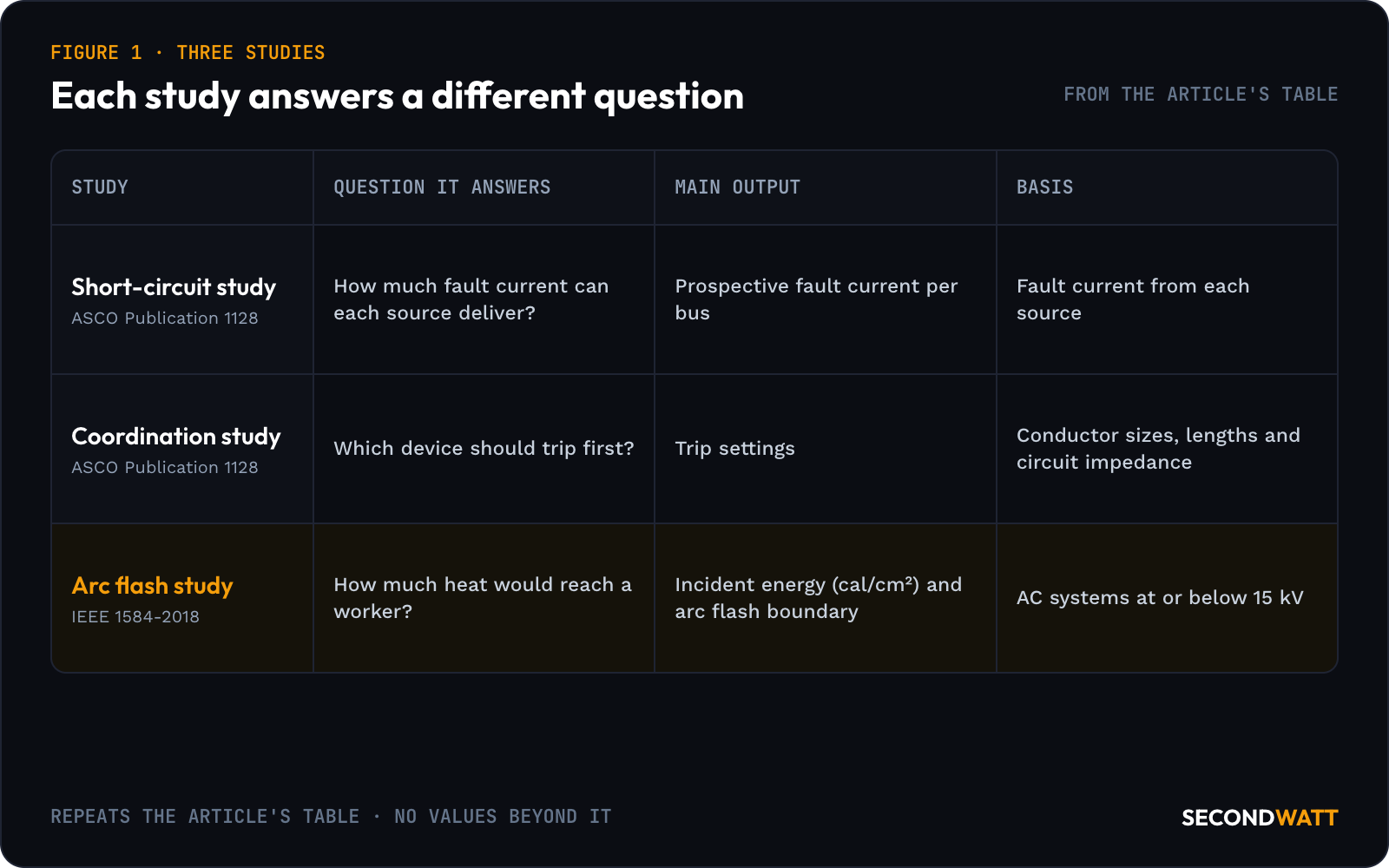
ASCO's Publication 1128, Rev. 38 notes that fault current falls the farther a device sits from the source. Optional short-time ratings cover transfer switches applied with breakers whose trip delays are set for selective coordination. S&C Electric notes that incident energy is typically highest when fault current is greatest or clearing takes longest.
What adding generators changes, worked#
In a microgrid, a fault anywhere in the AC system draws current from several distributed sources and possibly the utility, if grid connected. Several protective devices must then operate to clear it. Fault current can also differ widely between grid-tied and islanded operation and flow in both directions, two of the microgrid challenges S&C Electric lists. Distributed sources' fault current may also change with time.
Rotating machines typically supply six per-unit current or less and inverter-based sources two to three, while the bulk grid typically supplies significantly more. Islanded fault current can therefore be much lower than grid-tied. IEEE 1584-2018 recommends considering both maximum and minimum fault currents, in S&C's summary of the guide.
Lower fault current can still mean more incident energy. Where time-overcurrent protection guards against arcing faults, S&C Electric notes, incident energy may be higher at lower fault current because the devices take longer to clear. In microgrids, intermediate fault levels, such as different dispatch combinations of distributed energy resources, may also need evaluating.
The calculation below estimates one generator's initial symmetrical contribution.
Stamford's data sheet ES10458870 Rev. D, dated 28 Oct 2025, lists reactances for the S9L1D-F4 Wdg.312 alternator in per unit at stated kVA bases. At 480 V star, 60 Hz, the base is 4,464 kVA, the continuous Class H (125/40 °C) rating at 0.8 power factor, or 3,571 kW. The saturated direct-axis subtransient reactance (X″d) at that base is 0.111 per unit.
Worked example, initial symmetrical three-phase fault current at the alternator terminals:
Rated current = 4,464 kVA ÷ (1.7320508 × 0.48 kV) = 5,369 A
Fault contribution = 4,464 ÷ (1.7320508 × 0.48 × 0.111) = 48,373 A, or about 48 kA
The sheet's unsaturated X″d of 0.130 gives about 41 kA (4,464 ÷ (1.7320508 × 0.48 × 0.130) = 41,303 A). This is a simplified X″d estimate of symmetrical current at the terminals, with rated voltage before the fault. It leaves out cable and transformer impedance and the asymmetrical current the sheet also plots. Two identical sets on one 480 V bus would add about 97 kA on the same assumptions.
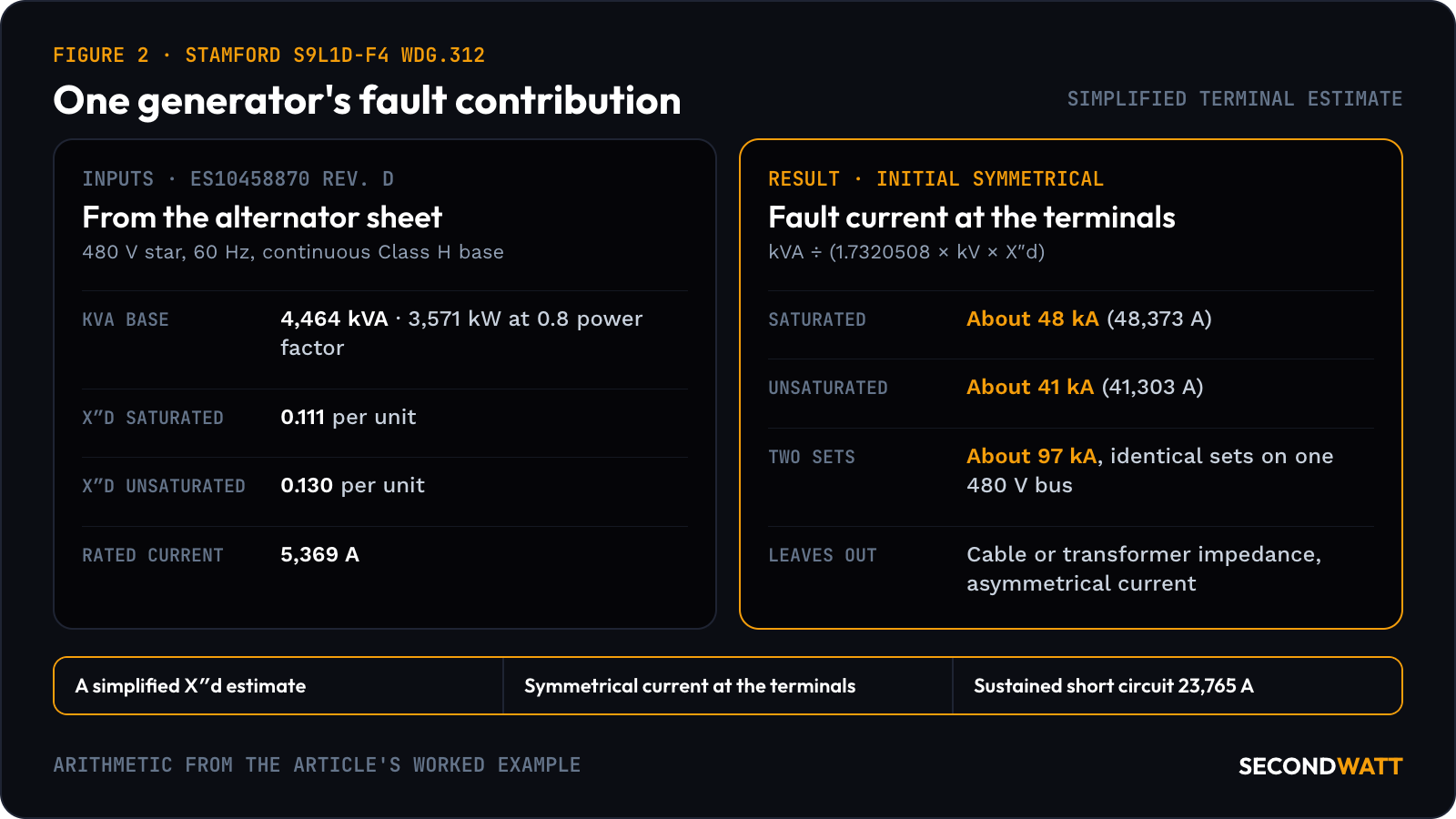
23,765 A — the sustained short circuit on Stamford's 60 Hz decrement curve for the S9L1D-F4 Wdg.312, separately excited, star-connected, at no-load excitation and rated speed.
On the 60 Hz symmetrical curve, current falls from its value at 0.001 seconds to a minimum, then recovers and settles at 23,765 A. That sustained value is constant irrespective of voltage, according to the sheet.
Load loss and impedance are among Prolec GE's standard commercial GSU tests, according to its 2024 Generation Step-Up Transformers data sheet. Test reports are available by serial number. The GSU specification guide and the GE Prolec GSU dossier cover the rest of the unit.
Used switchgear and its ratings#
A used lineup arrives with the ratings on its nameplate. What matters is how they compare with the fault current at its new bus, from every source that can feed it. For a transfer switch, find the prospective fault current from each source at the switch and the protective devices ahead of it. Then compare that current with the rating for that protection, as ASCO Publication 1128 sets out.
The protective device can change the answer by a factor of almost five. ASCO's J-frame 400 A transfer switch at 480 V is rated 200 kA with Class J (600 A maximum) or Class L (800 A maximum) current-limiting fuses. Specific breakers ASCO lists give the same 200 kA. Those values, in RMS symmetrical amps, come from ASCO's UL 1008 withstand and closing rating (WCR) table for its 300, 4000 and 7000 Series, dated 22 July 2026.
The time-based rating, marked at 0.05 seconds, is 42 kA, and 35 kA for switches with an overlapping neutral. The ATS sizing guide explains how to read those ratings.
Medium-voltage switchgear ratings from OEM documents (Siemens NXAIR 50 kA profile, June 2026; ABB UniGear ZS1 product page)#
| Lineup | Voltage | Breaking current | Short-time withstand | Peak withstand |
|---|---|---|---|---|
| Siemens NXAIR up to 17.5 kV, for 50 kA | ≤12 kV and 17.5 kV, 50/60 Hz | 50 kA | 50 kA (3 s) | 125/130 kA; 137 kA with generator circuit-breaker |
| ABB UniGear ZS1, single busbar | Up to 24 kV | Not stated on the page | 63 kA maximum (duration not stated) | Not stated on the page |
| ABB UniGear ZS1, double busbar / back-to-back (duplex) | Up to 24 kV | Not stated on the page | 31.5 kA maximum | Not stated on the page |
| ABB UniGear ZS1, double level | Up to 17.5 kV | Not stated on the page | 50 kA maximum | Not stated on the page |
The Siemens NXAIR 50 kA profile adds that NXAIR 50 kA switchgear carries internal arc classification IAC A FLR for an arc duration of 1 s. The ZS1 values on the ABB UniGear ZS1 page are range maximums; a used panel's own nameplate may sit below them. The NXAIR and UniGear ZS1 dossiers and the used MV switchgear guide cover what to request.
Labels, incident energy and PPE categories#
The study's results end up on the equipment. Under the edition current in December 2021, the arc flash risk assessment first determined whether an arc-flash hazard existed. If one existed, it then set work practices, the arc flash boundary and PPE, as Coache explained in a 2 Dec 2021 NFPA blog post. Both methods his post describes required the worst-case condition to be labeled on the equipment, regardless of the assigned task.
The 2024 edition offered a second route to PPE, in Coache's 2024 post. Its arc flash PPE category method reduced the need for extensive calculations for several common pieces of equipment. PPE is the last of six risk controls in NFPA's ordering on its Learn More About NFPA 70E page, after elimination, substitution, engineering controls, awareness and administrative controls.
In the US, OSHA's 29 CFR 1910.269 covers the operation and maintenance of electric power generation, control, transformation, transmission and distribution lines and equipment. That includes equivalent installations of industrial establishments. Supplementary generating equipment used to supply a workplace for emergency, standby or similar purposes only falls under Subpart S, per the section's note.
Section 1910.269 does not apply to construction work as § 1910.12 defines it. The exceptions are line-clearance tree trimming and work involving power generation installations, as § 1926.950(a)(3) specifies. Nor does the section apply to electrical installations, safety-related work practices or maintenance considerations covered by Subpart S.
Under paragraph (l)(8), the employer must assess the workplace to identify employees exposed to hazards from flames or electric arcs. For each employee exposed to arc hazards, paragraph (l)(8)(ii) requires the employer to make a reasonable estimate of the incident heat energy to which the employee would be exposed.
2.0 cal/cm² — when the incident-energy estimate exceeds this, 29 CFR 1910.269(l)(8)(v) requires the employer to ensure each employee exposed to electric-arc hazards wears protective clothing and equipment with an arc rating at least equal to the estimate.
That protection must cover the whole body, with five listed exceptions for hands, feet, head and face.
Appendix E treats IEEE Std 1584b-2011 as reasonable for arcs at 15 kV and below and not for arcs above 15 kV. Its table notes warn that the listed methods may not fully protect against internal faults in transformers and similar equipment. The same caution covers arcs in underground manholes or vaults. OSHA does not endorse any listed method.
Where Subpart S applies, OSHA's 29 CFR 1910.335(a)(1)(v) requires eye or face protection. Employees must wear it wherever electric arcs or flashes, or flying objects from an electrical explosion, could injure their eyes or face.
When to update a study#
Each change below alters an input or the method behind the study, and is a reason to ask whether the results still hold.
- Added sources: rotating machines and inverter-based sources both supply fault current, in S&C's figures, and the check in ASCO's Publication 1128 starts from the current "from each source."
- Paralleling and islanding: in S&C's microgrid paper, grid-tied and islanded fault levels can differ widely, and intermediate dispatch combinations may also need evaluating.
- Transformer changes: a new or replacement transformer can change the impedance between source and bus; use the tested value from the unit's report.
- Used gear moved to a new bus: its interrupting, withstand and WCR values are compared again with the fault current at the new location.
- Protective-setting changes: clearing time drives incident energy, in S&C's account, and the coordination study sets the trip settings, in ASCO's.
- A new edition of the method or standard: NFPA 70E's 2027 edition took effect on 6 May 2026, after the 2024 edition (effective 13 May 2023). IEEE approved a P1584 project on 25 September 2026 to supersede 1584-2018.
The 2027 edition was issued on 16 April 2026, according to the NFPA 70E page. The IEEE P1584 page shows that P1584 project as active. NFPA's NFPA 70 page lists the 2026 edition as the current NEC. OSHA's Appendix E still lists the 2002 edition of IEEE 1584 with its 2004 and 2011 amendments.
Scoping and buying a study#
A good request for proposal names the scope and the deliverables. IEEE 1584.1-2022 outlines "the minimum recommended requirements" for an owner to specify an arc-flash hazard calculation study, including scope of work and deliverables. For three-phase 50/60 Hz AC systems at 1,000 V and below, IEEE 1584.2-2025 gives checklists for collecting the data a study needs.
Each input above becomes an item on the data request:
- a current one-line diagram, with every source and its operating modes;
- utility fault data at the point of connection;
- generator data sheets with X″d, the X/R ratio and the decrement curve (Stamford's sheet lists a steady-state X/R ratio of 28.77);
- transformer nameplates and test-report impedances;
- cable sizes, quantities and lengths;
- breaker, relay and fuse types with their present settings;
- the ratings on each piece of used gear, including WCR tables for transfer switches.
The ANSI device numbers guide explains the device numbers on a one-line, and the generator circuit breaker guide covers generator protection points.
Ask for the deliverables in writing: the model, the short-circuit duty table, time-current coordination curves, incident energy by location and the labels. For a paralleled plant, also ask for results in each operating mode and for the mode that set each label; the paralleling switchgear guide explains those modes.
FAQ: arc flash studies#
Who can perform an arc flash study?#
The duty sits with the employer. Where 1910.269 applies, paragraph (l)(8)(ii) puts the incident-energy estimate on the employer and names no profession. The employer may choose a method outside Appendix E if it reasonably predicts the incident energy to which the employee would be exposed. According to NFPA, being a qualified person under NFPA 70E is task-specific, and it is the employer's responsibility to determine who is qualified for which task.
How much does an arc flash study cost?#
It depends on scope: the number of sources, buses and protective devices, the operating modes modeled and how much site data already exists. Ask bidders to price the same written scope, such as one built on IEEE 1584.1, so the quotes compare like for like.
Can one estimate cover several pieces of equipment?#
Under 1910.269, yes, within limits. Note 2 to paragraph (l)(8)(ii) lets the employer make broad estimates covering multiple system areas. It requires reasonable assumptions about the energy-exposure distribution, and the estimates must represent the maximum employee exposure for those areas.
Is NFPA 70E law?#
Not everywhere. Historically, 70E has not been officially required by state or federal law. NFPA reports that in December 2025, Delaware became the first state to incorporate it by reference, effective 1 January 2026. The standard assists in complying with OSHA 1910 Subpart S and 1926 Subpart K, according to NFPA's 70E page.
Does a DC system need a different method?#
Yes. S&C Electric notes that DC systems such as solar photovoltaic require different calculation methods than AC systems. The FPRF prospectus adds that IEEE 1584's guidance is limited to AC. The Fire Protection Research Foundation project would model DC arc flash, starting with an 800 Vdc data center application.
Sourcing switchgear and generation#
SecondWatt publishes equipment research and helps buyers source power equipment; it earns a fee when a sale it arranges closes. Buying gear for a site with new generation? Send a request that states the rating basis and the fault current at the intended bus. If you own a switchgear lineup leaving service, start at the switchgear seller page.