
Paralleling switchgear lets multiple generators supply a common electrical bus—the shared power connection feeding the loads—by combining generator controls with breakers and other power equipment. For an engineering, procurement and construction (EPC) team, the buying decision is to define which functions and physical equipment are included, which operating modes they support, and who proves the interfaces work together. A named paralleling controller is only part of that scope.
Key takeaways
- Trace the power path separately from the controls; supplying a control function does not establish who supplies the breaker, bus or facility interface.
- Synchronizing brings an incoming generator into alignment; sync-check permits connection under acceptable conditions. Load sharing does a different job after connection.
- Compare both real-power (kW) and reactive-power (kVAR) sharing, including evidence for the proposed combination of sets.
- Islanded operation and utility-parallel operation need separate scope descriptions. A controller feature is not permission to connect to the utility.
- Assign responsibility for load priorities, failure response and complete-system acceptance before treating offers as equivalent.
Follow power and control separately#
The power path carries electricity from the generators through their paralleling breakers to a common bus, then through the project's transfer or distribution equipment to the loads. Controls coordinate the generators and switching equipment through signals and commands. Cummins' June 2014 T-016 manual, section 2.4, separates generator sets, paralleling controls, supervisory controls, power-transfer controls and power sections for this reason.
Those are functional boundaries, not a requirement for one cabinet per function. A supervisory or “master” function coordinates the generator system with the facility; its scope depends on the facility's needs. Cummins' 2017 paralleling seminar, slides 25–26, illustrates the distinction between functions available at generator controls and broader system coordination, within that manufacturer's described architecture.
Use the following map to separate what carries power from what must exchange control information.
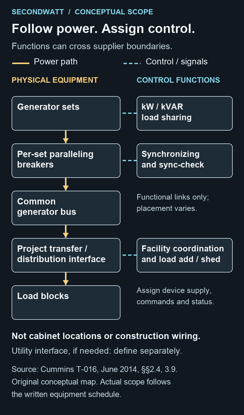
For each boundary, identify the supplier of the physical equipment and the party responsible for integrating its controls. Include control power—the electrical supply needed by the controls—and the transfer interface in that allocation. This gives the EPC a way to distinguish a controls package from a complete supplied power section without assuming that either offer is wrong.
Joining the bus is different from sharing the load#
Before a generator connects to an energized bus, its voltage, frequency and phase relationship must be suitable for connection, with a compatible phase sequence. Phase describes where the alternating voltage is in its cycle; phase sequence describes the order of the three phases. The synchronizer actively brings the incoming set into alignment, while sync-check provides permission to close when conditions are acceptable; the breaker makes the physical power connection. These are distinct functions, not necessarily separate hardware boxes (T-016, sections 2.3.3 and 3.4.3).
An unenergized, or “dead,” bus poses a different question: which set is allowed to connect first? First-close coordination establishes that choice before other sets join the energized bus. Request both functions in the proposed system description; an energized-bus synchronizing feature does not, by itself, describe dead-bus coordination (T-016, section 7.4.3.5).
Once connected, the sets must divide the load. In the isolated-bus arrangement described in T-016, sections 3.4.1–3.4.2, real-power sharing acts through the engine's fuel/governor control, while reactive-power sharing acts through the alternator's excitation or voltage-regulating control. Real power, measured in kW, supplies useful work; reactive power, measured in kVAR, is a separate part of the alternating-current load that the alternator must handle.
Proportional sharing means the same percentage of each set's relevant rating, rather than equal kW from differently sized sets. That is a steady-state objective: a settled operating condition does not establish how the combination behaves while loads change. Ask the generator supplier and integrator to identify both sharing channels and provide evidence for the proposed sets under steady and changing-load conditions; a successful synchronization demonstration answers only the joining question.
Compare the modes the project actually needs#
An islanded generator system supplies its local loads while electrically separated from the utility. Its controls regulate that local system and share its load. When connected in parallel with the utility, the control task changes: T-016 describes regulation of kW import/export and reactive power or power factor, plus collective synchronization when a multi-generator bus joins the utility (section 3.4.7). Power factor expresses the relationship between real and apparent power; it is a control objective here, not a generator-sizing shortcut.
Specify the intended modes before comparing feature lists. The mode comparison below connects each operating case to a proposed allocation of responsibility; confirm that allocation in the contracts.
| Operating case | What the offer must explain | Responsibility to agree |
|---|---|---|
| Islanded generator bus | Local voltage/frequency regulation; kW and kVAR sharing for the proposed sets | Generator supplier and integrator describe and demonstrate the configured behavior; project engineer accepts the basis |
| Utility parallel, if requested | Intended overlap or sustained operation; import/export intent; utility-mode control, collective synchronization and protection/interface scope | Integrator and project engineer define the interface; serving utility confirms applicable project requirements and permissions |
| Loss of a set or control function | Remaining capacity and control capability; load removal/restoration; response to controller, communications or control-power loss | Owner and engineer define required behavior; integrator and facility-interface suppliers demonstrate their assigned portions |
Comparison basis: Cummins T-016 (June 2014), sections 3.4.1, 3.4.7, 3.9, 5.4 and 7.5. Responsibilities are procurement recommendations to confirm, not universal contractual duties or a test procedure.
Utility-parallel capability is not authorization to export power or connect a particular installation. The manual's utility-interface discussion, section 7.5, makes the project and serving utility material to that decision. Its 2014 guidance does not establish today's local requirements; obtain the applicable project approval through the responsible engineer and utility. Intentional island operation should also be distinguished from unintentionally energizing a disconnected part of the utility system.
Load management connects the operating mode to the facility. Priority pickup adds groups of loads as capacity becomes available; load shedding removes loads in response to lost capacity or overload so the remaining capacity can serve higher-priority loads. Pickup and shedding priorities need not be identical (T-016, section 5.4). The owner and engineer should define the priorities, while the integrator and facility-equipment supplier agree which devices receive commands, return status and restore loads.
Make the interfaces and acceptance belong to someone#
Consider a hypothetical scope mismatch: one offer includes generator controls and load-shed commands, while the facility supplier excludes the devices and interfaces that act on those commands. “Load shedding included” has not closed the scope. Put the commanded device, its supplier, the status feedback and the party responsible for demonstrating the complete response into the same scope schedule. The offer is incomplete until those assignments are resolved; that does not establish that the equipment is incompatible.
Existing or dissimilar sets need the same discipline. Matching voltage and frequency alone does not establish compatibility: Cummins' section 7.4.3 considers engines, alternators, sharing controls and other control interfaces, including behavior during load changes. Request exact equipment identities, controller and applicable software revisions, interface drawings and evidence for the assembled combination. Its discussion of proprietary communications is dated 2014, so use it to frame an interface question, not to assume that current products from different manufacturers can never work together.
For supervisory controls, specify the behavior required after a controller, communications link or control-power supply is lost. Identify which automatic functions remain and which manual provisions are included, then assign demonstration responsibility. A “redundant master” label is not a complete description of the plant's response; the required supervisory functions follow the facility's needs (T-016, section 3.9).
Finally, separate component evidence, complete-system factory evidence and installed-system evidence. T-016's documentation and testing sections 8.1–8.2 distinguish those levels and call for project-specific documentation and interconnection information. A component record cannot substitute for evidence covering the interfaces and operating modes of the installed system. Agree the acceptance criteria and accountable integrator with the project engineer, and tie the records to the actual proposed configuration.
Send a sourcing request with the unit count, intended modes, equipment/function schedule, existing equipment identities where relevant, and named boundaries for facility integration and acceptance. Ask suppliers to mark inclusions, exclusions and unresolved interfaces against that same basis. This is a scope-comparison method; it provides neither protection settings nor design or operating approval.
SecondWatt facilitates introductions between equipment buyers and sellers and may earn a fee when an introduction proceeds. Request paralleling switchgear for your project with that scope attached, or use the switchgear hub for equipment discovery.