
N+1 and 2N do not, by themselves, tell you whether two data-center power proposals protect the same load against the same outage. N+1 adds spare capacity; 2N describes two complete capacity systems within a stated boundary. To compare the offers, follow the power from those systems to the equipment that must keep running. Healthy UPS modules can have ample capacity but no usable route to that load.
Use the comparison below to ask a supplier exactly which route remains available during maintenance or a fault, then have the responsible electrical engineer assess the proposed arrangement.
Key takeaways
- Set the same protected load and equipment boundary before comparing redundancy labels.
- A spare UPS module does not remove a shared downstream point of failure.
- Count capacity that can reach the load, not just modules that remain healthy.
- Maintenance alone and another fault during maintenance are different requirements; plain 2N does not add a spare module to each path.
- Check how the load accepts the alternate feed. Capacity arithmetic establishes neither uninterrupted operation nor Tier certification.
Ask where the redundancy ends#
An uninterruptible power supply, or UPS, is part of the power system serving the protected equipment. In this context, N means the capacity needed by that equipment. N+1 adds one redundant unit or module beyond that need; the comparison still starts with the same load. Schneider Electric's UPS configuration paper, Rev 4, defines N around the protected load.
The next question is what the extra module protects against. In the paper's parallel redundant arrangement, compatible UPS modules work together on a common output bus—the electrical connection that collects their outputs. When one module leaves service, the others must immediately accept its share of the load. That requirement concerns both sufficient capacity and the equipment's ability to respond.
The common bus remains a dependency. Figure 3 and its discussion distinguish a module failure from failure of that shared connection. The maintenance bypass shown there routes power around the UPS modules but still feeds shared downstream distribution; it is not another independent protected path to the load.
For an offer labeled 2N, ask which two complete systems are being duplicated and how far their separate routes extend. Do not read it as 2(N+1), which adds module redundancy within each of two systems. Schneider's Figure 7 is explicitly a 2(N+1) example, so its spare-module capability must not be assumed for a plain 2N offer.
Follow two routes to the same 300 kW load#
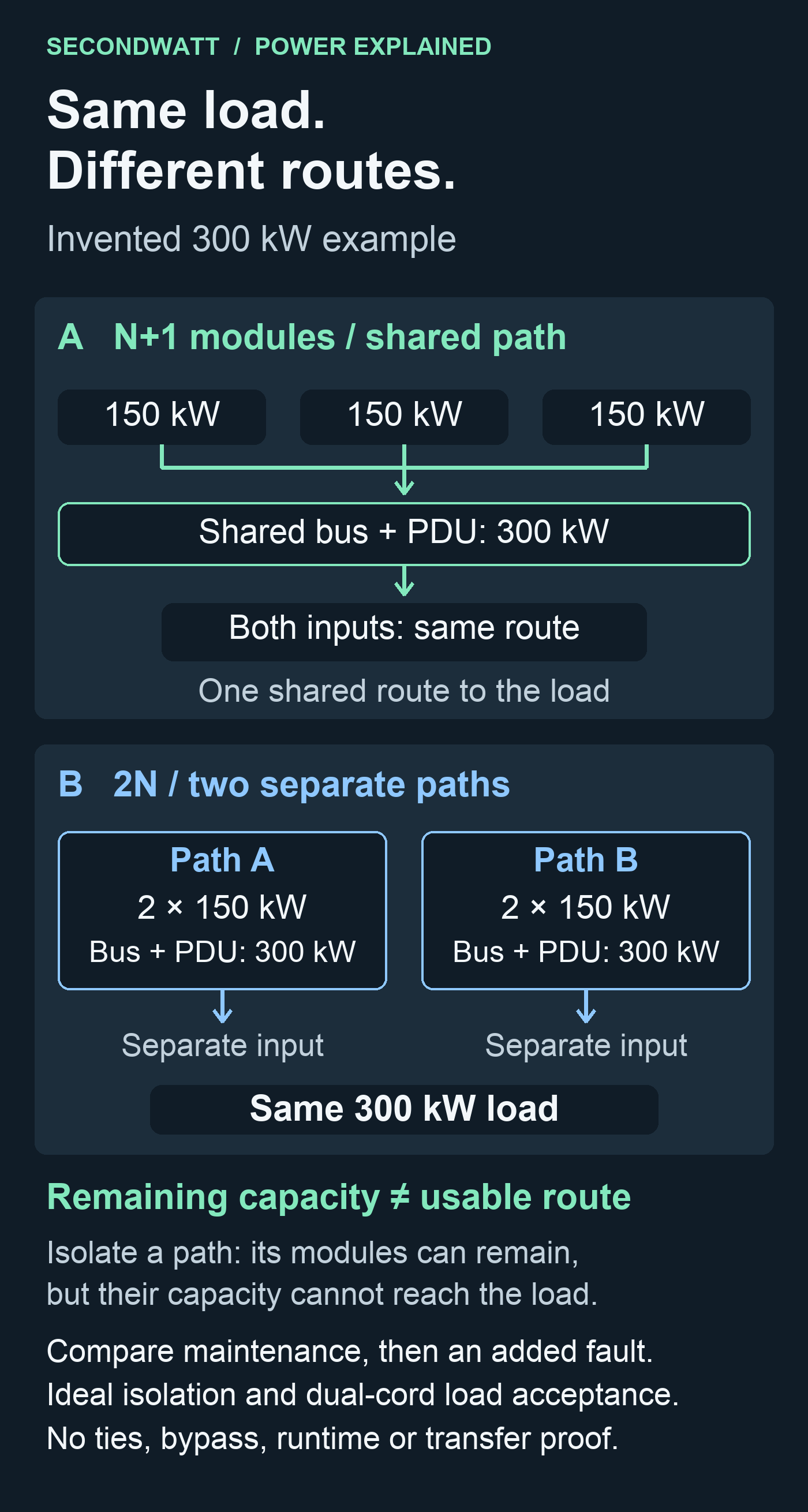
The following invented example compares capacity and connectivity, not products or tested performance. Both arrangements serve the same 300 kW aggregate load; kW measures real power. The boundary begins at the UPS module outputs and includes the output buses, power distribution units (PDUs), feeders and load inputs.
- Arrangement A: N+1 modules, shared path. Three compatible, synchronized 150 kW modules feed one common bus and PDU. Both load inputs depend on that route.
- Arrangement B: 2N, two paths. Each path has two 150 kW modules, its own bus and PDU, and a separate load input. Each path has enough module capacity for the whole load, with no spare module on either path.
All ratings are invented usable capacities: each path and each load input can support 300 kW, with no losses, derating or overload allowance. The load is assumed to accept its full demand through either input without interruption. Faults isolate cleanly, healthy modules immediately accept redistributed load, and all remaining modules have adequate input power; there are no connecting ties or bypass routes in this model.
Utility supply, generators, battery duration, cooling, shared controls and room hazards are outside the comparison. Electrical protection, switching time and transient response—the behavior during the change from one operating state to another—also require separate assessment. These assumptions let us test a route, not certify a facility or predict a real transfer.
Trace each arrangement from the modules to the load before comparing the outage cases.
Separate maintenance from an added fault#
The table applies only to the example above. Remaining module capacity counts modules not removed or failed, including those stranded behind an isolated path. Reachable capacity counts only what the available routes could carry to the load, limited by each route's rating; it is not the power actually being consumed.
| Event in the invented example | Remaining module capacity | Reachable capacity | Enough for the full 300 kW? |
|---|---|---|---|
| A: one module removed for maintenance | 300 kW | 300 kW | Yes, conditionally |
| A: one module under maintenance, then another module fails | 150 kW | 150 kW | No |
| A: shared path isolated for maintenance | 450 kW | 0 kW | No |
| B: one module on path A fails; both paths remain available | 450 kW | 450 kW | Yes, conditionally |
| B: path A isolated for maintenance | 600 kW | 300 kW | Yes, conditionally |
| B: path A under maintenance, then one module on B fails | 450 kW | 150 kW | No |
| B: path A under maintenance, then path B fails | 600 kW | 0 kW | No |
“Yes” means only that enough capacity is logically reachable under the stated assumptions. It does not demonstrate a successful transfer or uninterrupted service; “No” identifies a capacity shortfall without predicting which equipment shuts down. A cleanly isolated shared-path fault in A gives the same zero-reachability result as its path-maintenance row; an isolated path-A fault in B leaves the same 300 kW reachable as path-A maintenance.
The procurement distinction is visible in the two maintenance rows. A can lose a module and retain enough capacity, but cannot isolate its common route while serving the load through that route. B can isolate a whole path in this example, but an additional module failure on the remaining path leaves it short. If the requirement includes that second event, a proposal meeting only maintenance-alone capacity needs further engineering work before it can be treated as equivalent scope.
Ask the supplier to identify the specific component taken out of service and trace the surviving route. “Maintainable” is incomplete unless it says what can be maintained, which load remains supplied and whether another fault is included.
Check the last connection to the load#
Two upstream paths help only if the equipment can use them. Dual-cord equipment has two power connections, but the engineer must confirm that either input and its supply path can support the complete demand. The example assumes that capability; the presence of two cords alone does not establish it.
Change B to a single-cord load attached only to path A, with no transfer device. Isolate A and none of the remaining capacity can reach that load, even though path B is healthy. Schneider's discussion of single-cord loads identifies a transfer arrangement as a way to connect such equipment to alternate supplies.
For a real proposal, ask: “What moves this load to the other feed, and what evidence shows it can tolerate that change?” Have the engineer assess the transfer device's rating, compatibility, operating time and own failure case. Do not infer ride-through—the load continuing to operate through a disturbance—from the capacity figures alone.
Turn the label into comparable equipment scope#
A useful proposal response names the route and its limits. For B, the capacity description could read: “300 kW protected load; two separate 300 kW paths from UPS outputs through distribution to load inputs; path A isolated for maintenance; path B retains 300 kW reachable capacity. With one further 150 kW module failure on B, only 150 kW remains reachable.” That is a description of the invented case, not a specification to copy into a construction contract.
Ask each supplier for the equivalent description against your engineer's load and named events. Reconcile differences using the maintenance and added-fault comparison: a shared route, a transfer dependency or an excluded event changes what the offer actually covers. Keep the proposed means of maintaining service and its supporting performance evidence separate from the capacity calculation.
Keep certification separate too. Uptime Institute's explanation of component counts and Tier certification rejects a count-based determination; its Tier overview describes an infrastructure assessment. Neither N+1 nor 2N on an equipment offer establishes facility Tier certification. This comparison makes no Tier classification or uptime claim.
Once the engineer has defined the protected load, required events and equipment boundary, use the UPS systems hub for equipment context. SecondWatt facilitates introductions between equipment buyers and sellers and may earn a fee when an introduction proceeds. To request equipment for the defined scope, provide those requirements and identify which distribution and load-transfer responsibilities are included or remain with other parties.