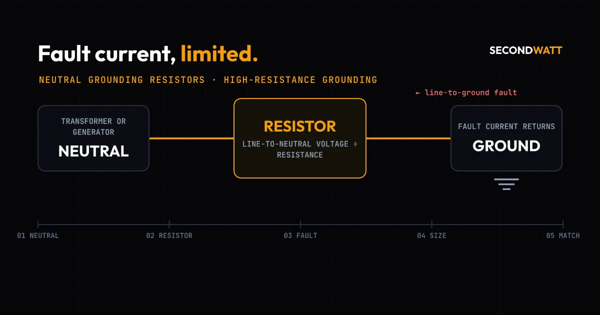
A neutral grounding resistor (NGR) connects the neutral of a transformer or generator to ground through a resistor. When one phase faults to ground, the fault current returns through that resistor, which caps it at a value chosen at design. High-resistance grounding sets the cap low, so a low-voltage system can keep running with one fault on it. Low-resistance grounding sets it high enough for relays to trip the faulted circuit, usually within a few seconds.
That choice travels with the equipment. A transformer's winding connection, a generator's neutral arrangement and the ground-fault relays in a switchgear lineup are each built around one scheme. When those pieces come from different sites, the method, the resistor rating and the relaying have to agree before the system is energized.
Key Takeaways
- The resistor sets the ground-fault current. Fault current through an NGR is close to the line-to-neutral voltage divided by its resistance, so the designer picks the current.
- High-resistance grounding rides through a first fault. Post Glover puts currents typically under 25 A at 600 V or less; Eaton warns some UPSs then inhibit bypass transfer.
- Low-resistance grounding trips instead. Post Glover describes typically 50 A or more, so relays clear the fault, usually within a few seconds; the circuit shuts down on the first fault.
- Sizing is Ohm's law checked against charging current. At 480 V, an illustrative 5 A needs 55.4 ohms; Bender's guideline requires at least the system's charging current.
- Mixed used equipment must agree on grounding. Each source's neutral, the NGR's voltage, current and time rating, and the relay settings must match before energizing.
What a neutral grounding resistor does#
Post Glover's 2012 technical guide NG112-06 defines two kinds of grounding. System grounding is the deliberate connection of earth ground to the neutral point of a transformer, generator or system, either solidly or through a current-limiting device. Equipment grounding is the separate connection of earth ground to non-current-carrying conductive parts such as conduit, enclosures and motor frames. An NGR is one such current-limiting device.
Bender's guideline on sizing an NGR, revision 2019.01, describes the resistor as purpose-made. It is connected between system neutral and ground to limit both ground-fault current and ground-fault voltage. During a line-to-ground fault, the normal line-to-neutral voltage appears across the resistor. The current is then practically that voltage divided by the resistance.
Take a 4,160 V system grounded through 12 ohms, Post Glover's own example. The line-to-neutral voltage is 4,160 ÷ √3 = 2,400 V, so the fault current is 2,400 ÷ 12 = 200 A. The resistor is rated by its line-to-neutral voltage, its initial current and its time rating.
Without that path, distributed capacitance still couples every conductor to ground, and a fault on one phase puts full line-to-line voltage, 1.73 times normal, on all insulation in the system. Post Glover adds that switching a circuit with a ground fault on it can cause transient overvoltages of several times normal from line to ground.
Grounding methods compared#
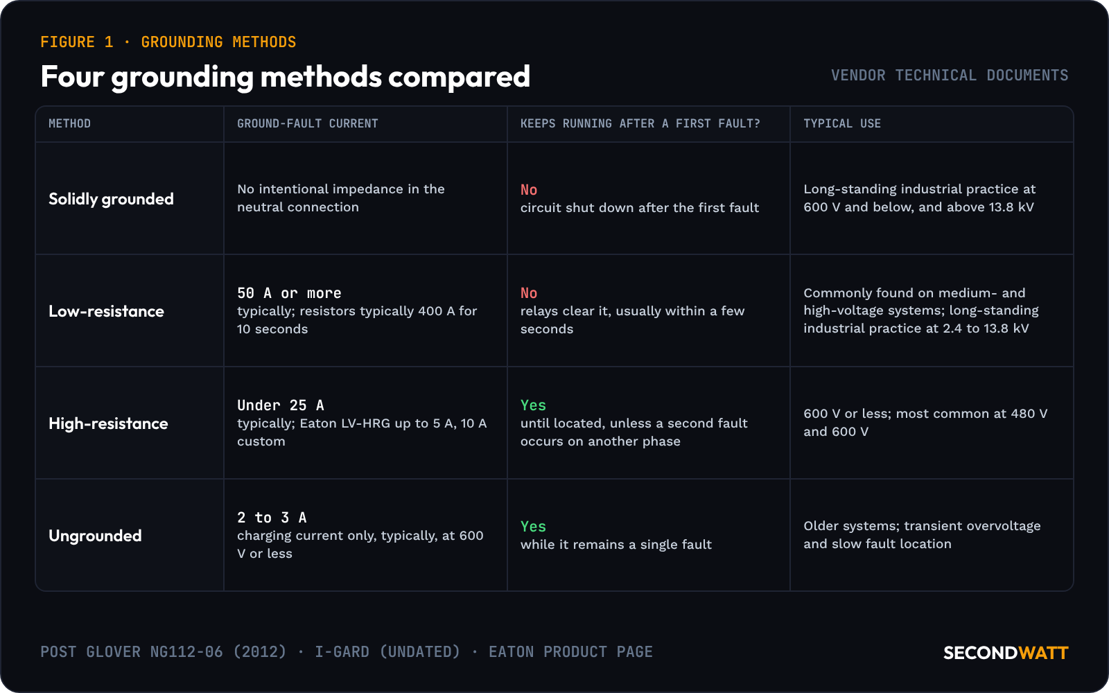
Four arrangements recur in resistor makers' documents; each cell names its vendor source.
Grounding methods compared: ground-fault current and continuity, from Post Glover, I-Gard and Eaton technical documents#
| Method | Ground-fault current | Keeps running after a first ground fault? | Typical use |
|---|---|---|---|
| Solidly grounded | No intentional impedance in the neutral connection (Post Glover) | No: the circuit is shut down after the first fault (Post Glover) | Long-standing industrial practice at 600 V and below, and above 13.8 kV (Post Glover) |
| Low-resistance grounded | Typically 50 A or more; resistors typically rated 400 A for 10 seconds (Post Glover) | No: relays clear the fault, usually within a few seconds (Post Glover) | Commonly found on medium- and high-voltage systems; long-standing industrial practice at 2.4 to 13.8 kV (Post Glover) |
| High-resistance grounded | Typically under 25 A (Post Glover); up to 5 A on Eaton's LV-HRG, custom up to 10 A (Eaton) | Yes, until the fault is located, unless a second fault occurs on another phase (Post Glover) | 600 V or less (Post Glover); most common at 480 V and 600 V (Eaton) |
| Ungrounded | Capacitive charging current only, typically 2 to 3 A at 600 V or less (I-Gard) | Yes, while it remains a single fault (Post Glover) | Older systems; exposed to transient overvoltage and slow fault location (Post Glover) |
IEEE's recommended practice here is IEEE 3003.1-2019, System Grounding of Industrial and Commercial Power Systems. IEEE's standards page lists it as active, published 9 August 2019.
Resonant grounding instead uses an inductor matched to the system capacitance. I-Gard's NGR design and application note says resistance grounding is preferred in the US, mostly on economics and complexity.
High-resistance grounding at 480 V#
Eaton's low-voltage HRG page calls high-resistance grounding mainly a low-voltage arrangement, most common in 480 V and 600 V systems. Eaton's LV-HRG limits ground-fault current to up to 5 A, with custom units up to 10 A. I-Gard treats 10 A as the good-engineering-practice line between high and low resistance, and its rule of thumb puts HRG on most systems of 5 kV and less.
The appeal is continuity. Post Glover notes that the fault can stay on the system until it is located, then be isolated at a convenient time. HRG can also be added to an existing ungrounded system without new fault-clearing relays and breakers.
In a December 2013 white paper, Eaton says an HRG system would be desirable for mission critical applications. Currents typically under 10 A remove the need to trip immediately. The same paper flags a catch for UPS loads. Some UPSs view a neutral-to-ground voltage as a fault and inhibit transfer to and from bypass, so HRG may not be recommended for powering UPSs or other information and communication technology loads.
The costs come with the first fault. The two unfaulted phases rise to line-to-line voltage, a 73% increase in insulation stress. As Post Glover notes, a second fault on another phase before the first is cleared becomes a line-to-line fault.
Monitoring is therefore part of the purchase: Eaton's Digital HRG lists resistor health monitoring with open and short alarms, plus test functions for the HRG and its relay.
Low-resistance grounding on medium-voltage systems#
Low-resistance grounding limits ground-fault current to typically 50 A or more, so protective relays and current transformers can operate. The relays then clear the fault, usually within a few seconds. The circuit shuts down on the first fault, as Post Glover's guide and its 2024 low-resistance NGR sheet both describe.
400 A for 10 seconds — the rating Post Glover calls typical for low-resistance grounding resistors, which it says are commonly found on medium- and high-voltage systems.
The current is set from both ends. It must exceed the system's charging current, so I-Gard says 100 to 400 A is usually selected. It must also be large enough for relays to see: Post Glover says ground-fault relays are generally selected to operate at 5% to 20% of the resistor's maximum current.
Element material matters at these currents. Resistance rises with temperature, and so the fault current falls during the rated time. I-Gard recommends an element temperature coefficient of no more than 0.0002 ohm per °C, so current falls no more than 20% from ambient to full operating temperature.
Sizing the resistor#
Bender's guideline names three ratings that decide the selection of an NGR: voltage, time and let-through current. The voltage rating is the system's line-to-neutral voltage, the voltage across the resistor during a bolted single-phase ground fault. Resistance follows from Ohm's law, and dissipated power is the line-to-neutral voltage times the current.
Worked example, with illustrative currents. The 5 A and 400 A values match what I-Gard calls typical for HRG at 600 V or less and what Post Glover calls typical for LRG.
- 480 V system: 480 ÷ √3 = 277.1 V line to neutral. At 5 A, R = 277.1 ÷ 5 = 55.4 ohms, and P = 277.1 × 5 = 1,386 W, continuous.
- 13.8 kV system: 13,800 ÷ √3 = 7,967 V line to neutral. At 400 A, R = 7,967 ÷ 400 = 19.9 ohms, and P = 7,967 × 400 = 3.19 MW for the rated time.
The 480 V result matches one of I-Gard's own answers, which names a continuously rated 55-ohm, 277 V resistor for a 2 MVA, 480 V generator set. At the 13.8 kV rating, 10 seconds at 3.19 MW is about 31.9 MJ of heat, taking the current as constant.
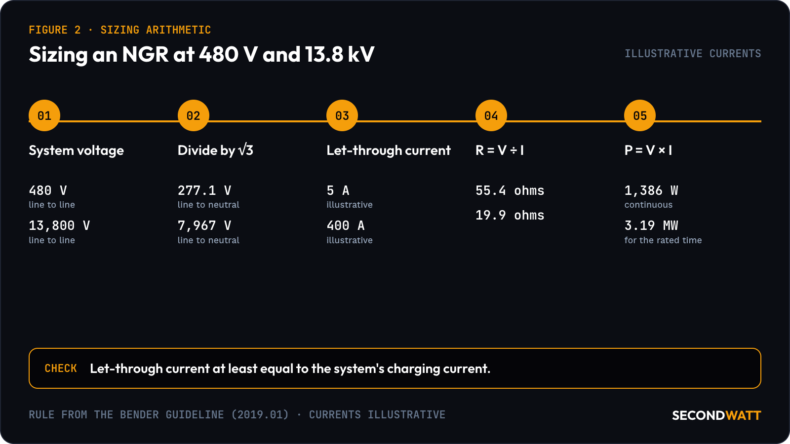
The let-through current has a floor. Bender's guideline says the rating "must be equal to or greater than system charging current" to eliminate the possibility of transient overvoltage. Post Glover and I-Gard state it as a current greater than the system's total capacitance-to-ground charging current.
0.5 A per MVA — Bender's conservative estimate of charging current on low-voltage power-distribution systems, rising to 1 A per MVA on medium-voltage systems.
Post Glover gives the same figures per 1,000 kVA of transformer capacity. Applied to an illustrative 2,500 kVA, 480 V system, they give 0.5 × 2.5 = 1.25 A, a quarter of the illustrative 5 A. An illustrative 20 MVA, 13.8 kV system gives 1 × 20 = 20 A. I-Gard uses 1.5 A per MVA in one answer on a 6.6 kV system, which gives 30 A; either estimate sits far below 400 A.
At that minimum, Bender says, fault location and selective coordination are hard to achieve, and it recommends a tripping ratio of 5 or more between let-through current and detection setting. I-Gard's note says charging current comes almost entirely from feeders and surge arrestors or capacitors. Bender's guideline adds that it changes when loads are switched or cable is added or removed. It can also be measured on an existing system.
Post Glover lists the IEEE 32-1972 time ratings as 10 seconds, one minute, ten minutes, extended time and steady state. Bender typically recommends a 10-second NGR for tripping systems; alarm-only systems need a continuous rating. IEEE 32 was superseded by C57.32-2015, which IEEE now lists as inactive-reserved since 26 March 2026; revision PC57.32 is an active project.
Grounding transformers and generator neutrals#
A grounding transformer creates a neutral where none is available. The neutral may be missing on older 600 V and lower systems and on many existing 2,400 to 6,900 V systems, particularly delta and underground wye systems. Post Glover says the new neutral is grounded directly or, more commonly, through an NGR.
A zigzag is a three-phase, dry-type autotransformer with no secondary winding, and it is the more common of the two. A wye-delta unit has a wye primary on the system and a delta secondary connected to nothing external. In Post Glover's description, both present high impedance to normal current and low impedance to zero-sequence fault current.
Post Glover's guide and its 2015 zigzag sheet set out where to connect them. Either type should be connected on the line side of the main breaker, as close as possible to the power transformer's secondary, one per power transformer. No more than one should be connected to the same section of the system at the same time.
Where the neutral is available, a single-phase distribution transformer can be used instead, an arrangement Post Glover calls particularly well suited to generators. Its primary runs from the neutral to ground, and a loading resistor sits across the secondary, normally 240 or 120 V. In Post Glover's 2015 data sheet, the resistor is normally sized for a primary ground-fault current of 2 to 12 A and typically rated for one minute or continuous duty. The secondary resistance is reduced by the square of the turns ratio.
For medium-voltage systems, Bender notes that past practice sometimes used this arrangement, and it recommends an NGR connected directly to the neutral as simpler and more economic.
Several generator manufacturers require resistance grounding, I-Gard notes, because the generators are not rated for ground faults, which are often higher than three-phase faults. I-Gard adds that this may not be an issue at 600 V or below, but usually is as the voltage class rises.
For a bus-connected generator whose system charging current exceeds 10 A, I-Gard recommends a hybrid: a 5 A path and a 100 A path in parallel. On an internal generator fault, the 100 A path trips with the generator breaker, leaving 5 A in the winding.
IEEE C62.92.2-2017, an active IEEE guide, covers the factors in choosing the class and means of neutral grounding for synchronous generator systems connected to electric utility systems. On a step-up unit with a delta generator-side winding, such as the YNd1 units in the GSU transformer guide, the transformer gives the generator bus no neutral. That ground reference then comes from the generator neutral of the gas turbine set, or from a grounding transformer.
Grounding checks when buying used equipment#
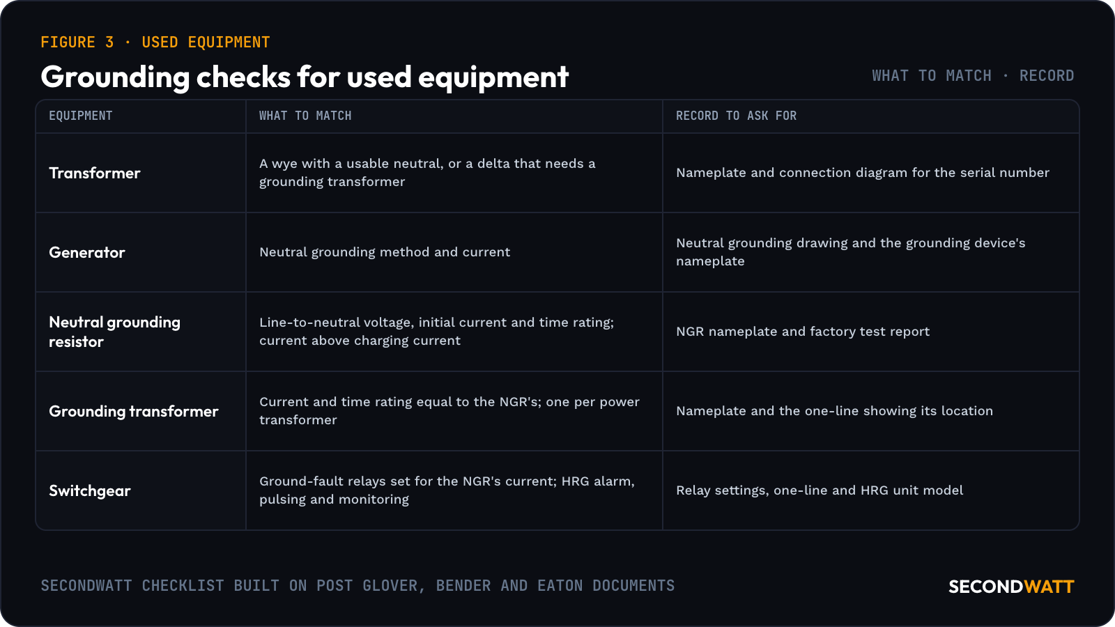
A used transformer, generator and switchgear lineup can each be sound and still not work together.
Grounding checks for used equipment (SecondWatt checklist built on Post Glover, Bender and Eaton documents)#
| Equipment | What to match | Record to ask for |
|---|---|---|
| Transformer | Secondary winding: a wye with a usable neutral, or a delta that needs a grounding transformer | Nameplate and connection diagram for the serial number |
| Generator | Neutral grounding method and current, such as a distribution transformer with loading resistor | Generator neutral grounding drawing and the grounding device's nameplate |
| Neutral grounding resistor | Line-to-neutral voltage, initial current and time rating; current above the new system's charging current | NGR nameplate and factory test report (applied-potential and resistance-tolerance tests) |
| Grounding transformer | Current and time rating equal to the NGR's; one per power transformer | Nameplate and the one-line showing its location |
| Switchgear | Ground-fault relays set for the NGR's current; HRG alarm, pulsing and monitoring | Relay settings, one-line and HRG unit model |
As Bender's guideline notes, a resistor rated 10 seconds for a tripping system cannot serve an alarm-only HRG, which needs a continuous rating. IEEE 32, as Post Glover summarizes it, requires an applied-potential test and allows a resistance tolerance of plus or minus 10%.
Post Glover places the ground connection at the source of each separately derived system, at the generator or power transformer neutral. When a lineup is rebuilt from used parts, each new source needs its own ground point. The used pad-mount checklist covers the transformer neutral arrangement, and the ATS sizing guide explains why pole count follows the grounding scheme.
Eaton offers HRG as an option within its Magnum low-voltage switchgear, motor control centers and switchboards. A used Magnum lineup such as the Eaton Magnum DS may or may not carry one. On medium-voltage lineups, the used MV switchgear guide covers the relaying records.
FAQ: neutral grounding resistors#
Is high-resistance grounding allowed in data centers?#
It can be, on conditions. Appendix B of Eaton's white paper restates NEC Article 250.36 as barring HRG unless maintenance and supervision ensure only qualified persons service the installation, ground detectors are installed and line-to-neutral loads are not served. Its main text also limits HRG to three-phase installations where continuity of service is required. Those conditions are as Eaton stated them in December 2013.
NFPA's NFPA 70 page lists the 2026 edition of the National Electrical Code as current. The engineer of record reads the adopted edition's text for these conditions.
What happens when a ground fault occurs on an HRG system?#
Bender's guideline gives the fault current as the resistor current plus the system's charging current. A pulsing system, it says, helps find the faulted feeder by periodically changing the resistor current, typically by switching in a second parallel resistor. Eaton's Digital HRG offers a 5 A pulsing current on its 5 A and 10 A configurations.
Can an HRG system serve line-to-neutral loads?#
Not from the resistance-grounded neutral. During a fault, the neutral sits at line-to-neutral voltage above ground, so Post Glover says it cannot be used for loads such as single-phase lighting. Figure 9 of the guide shows a 208Y/120 V section supplied through its own transformer and grounded separately.
What is the difference between an NGR and a grounding transformer?#
An NGR limits current; a grounding transformer creates the neutral it connects to, which a wye source with a usable neutral does not need. With a zigzag, Post Glover notes, fault current is then limited only by the fault resistance, the NGR and the zigzag's small reactance.
What makes a neutral grounding resistor fail?#
Thermally induced mechanical stress, corrosive air, high humidity, vibration and wildlife are the causes Bender lists. An open NGR leaves the system ungrounded, and a later ground fault produces no zero-sequence current and goes undetected unless other measures are in place. Bender therefore recommends continuous NGR monitoring in every application, able to find an open resistor whether the system is energized or not.
Matching the grounding scheme#
SecondWatt publishes equipment research and helps buyers source power equipment; it earns a fee when a sale it arranges closes. Buyers matching transformers, generators and switchgear to one grounding scheme can request equipment with the NGR and neutral details listed. Owners of grounding or distribution gear can sell switchgear.